

/image%2F1363385%2F20160517%2Fob_ff792f_trent.jpg)
Sur le pas des hélices - About propeller's pitch
Je me suis récemment procuré un article intéressant sur les hélices de modèles réduits: Analytical – Experimental Comparison for Small Electric Unmanned Air Vehicle Propellers de Michael OL, Cale ZEUNE et Mike LOGAN. L'article n'est malheureusement pas disponible gratuitement...
Un des point que j'ai retenu, parmi d'autres, est la volonté de prendre en compte le pas, ce dernier n'entrant pas dans la définition des coefficients utilisés habituellement.
Bien sûr, c'est un problème que je m'étais déjà posé, mais d'une manière un peu différente (plus du bidouillage de gars inculte qu'un véritable trait de génie j'en ai peur !).
Les auteurs de l'article propose une mise à l'échelle en introduisant le pas de la manière suivante:
- le coefficient de traction Ct est multiplié par le rapport diamètre/pas (D/P),
- le coefficient de couple Cq (Cp = 2π*Cq) est multiplié par le rapport D/P à la puissance 3/2,
- le rapport d'avancement J=v/nD est multiplié par le rapport D/P.
Cette méthode est justifiée comme suis:
I recently purchased an interesting article on RC aircraft's propellers: Analytical - Experimental Comparison for Small Unmanned Air Vehicle Propellers by Michael OL, Cale ZEUNE and Mike Logan. The article is not available for free ...
One point that interested me, among others, is the willingness to take pitch into account, which does not fall within the definition of the coefficients are usually used.
Of course, this is a problem that I had already thought about, but in a slightly different manner (more an uneducated guy's guess then a real stroke of genius I'm afraid!).
The authors of the article propose a scaling by introducing the pitch as follows:
- The thrust coefficient Ct is multiplied by the diameter to pitch ratio (D / P),
- The torque coefficient Cq (Cp * = 2π Cq) is multiplied by the D / P ratio to the power 3/2,
- Advance ratio J = V / nD is multiplied by the D / P ratio.
This approach is justified this way:
J'ai appliqué cette méthode aux données sur les hélices APC sport de 8 pouces (source UIUC).
I've applied this method to data on 8-inch APC sport propellers (source UIUC).
Pour le coefficient de traction:
Thrust coefficient:

Pour le coefficient de puissance:
Power coefficient:

De mon côté, j'ai eu une approche un peu différente. Je suis également parti du rapport D/P, plus exactement j'ai pris P/D mais la logique reste la même.
Comme J est une expression de l'angle entre le plan de rotation et la direction de l'air arrivant sur les pales de l'hélice en rotation, que P/D est une expression du calage donc de l'angle entre le plan de rotation et l'angle de la corde d'une section de pale, J - P/D doit en théorie être une expression de l'angle d'attaque de la pale, or en dessous de l'angle de décrochage la portée varie avec l'angle d'attaque, donc Ct devrait faire de même.
On my side, I had a slightly different approach. I also start from D / P, more precisely I took P / D but the logic remains the same.
Since J is an expression of the angle between the plane of rotation of the propeller and the direction of the incoming air on the blades, since P / D is an expression of blade angle, therefore of the angle between the plane of rotation and the angle of the chord of a blade section, then J - P / D should theoretically be an expression of the angle of attack of the blade, and since below the stall angle lift may vary with angle of attack, Ct should do the same.
Pour les hélices APC sport de 8 pouces:
Coefficient de traction:
For the 8-inch APC sport propellers:
Thrust coefficient:

Pour ce qui est du coefficient de puissance, on obtiens une bonne concordance en le multipliant par D/P, je n'explique pas plus la logique.
Coefficient de puissance:
Regarding the power coefficient, we get a good agreement by multiplying it by D / P, I do not explain more logic.
Power coefficient:

On note une relativement bonne concordance, surtout aux faibles angles d'attaque (faibles J - P/D ou grands J), le comportement post décrochage est en revanche plus complexe. On remarque que les courbes de Ct / J-P/D semblent se répartir en deux groupes qui correspondent en fait aux 3 plus petits pas d'un côté (8x4, 8x5 et 8x6) et aux plus grands pas de l'autre (8x7, 8x8, 8x9 et 8x10).
L'étape suivante a été d'intégrer à ma feuille de calcul "Tetacalc" la possibilité de "changer" le pas d'une hélice connue en appliquant les principes décrits plus haut. La méthode utilisée est la suivante:
- pour le Ct : une polynomiale décrivant les variations du Ct original selon J est établit, le Ct modifié est ensuite calculée en appliquant la fonction à J auquel est additionnée la différence entre le P/D d'origine et le P/D avec le pas modifié.
- pour le Cp : le procédé est le même sauf que l'on établit la polynomial à partir de Cp*D/P.
L'inconvénient de cette méthode est l'extrême imprécision des prédictions aux faibles avancements lorsque l'on cherche un pas plus élevé que celui d'origine.
There is a relatively good agreement, especially at low angles (low J - P/D or high J), the post stall behavior is rather more complex. We note that the Ct / (J- P/D) curves appear to fall into two groups which are actually the three smaller pitch on one side (8x4, 8x5 and 8x6) and the greatest ones on the other (8x7, 8x8 , 8x9 and 8x10).
The next step was to integrate to my worksheet "Tetacalc" the ability to "change" the pitch of a known propeller by applying the principles described above. The method used is as follows:
- For Ct: a polynomial describing the variations of the original Ct versus J is established, the modified Ct is then calculated by applying the function to J at which is added the difference between the P / D of origin and P / D with changed pitch.
- For Cp: the process is the same except by establishing the polynomial from Cp * D / P.
The disadvantage of this method is the extreme poor predictions at low advance ratio when trying to simulate a higher pitch than the original.
Le bidouillage doit ensuite être vérifié dans Tetacalc.
This should then be verified in Tetacalc.
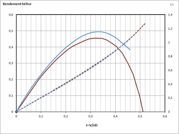
Ci-dessous, les courbes bleues sont celles d'une APC 8x4 Sport simulée d'après une APC 8x5 Sport, les rouges sont celles d'une APC 8x4 Sport (données UIUC) :
Coefficients de traction et puissance (en pointillés):
Below, the blue curves are those of an APC 8x4 Sport simulated from an APC 8x5 Sport, red ones are those of an APC 8x4 Sport (UIUC data):
Thrust and power (dotted) coefficients:

Efficience (rendement) :
Efficiency:

Idem, en bleue une APC 8x6 Sport d'après une APC 8x5 Sport, en rouge une vraie APC 8x6 Sport (données UIUC) :
Same, blue is an APC 8x6 Sport from an APC 8x5 Sport, red is a true APC 8x6 Sport (UIUC data):


Une APC 9x7.5 Slow Fly simulant une APC 9x6 Slow Fly en bleu, et une véritable APC 9x6 Slow Fly en rouge (données UIUC) :
An APC 9x7.5 Slow Fly simulating an APC 9x6 Slow Fly (blue) and a real APC 9x6 Slow Fly (red) (UIUC data) :


Même principe avec une APC 12x12 Thin Electric transformée en APC 12x10 Thin Electric (d'après données BART) :
Same idea with an APC 12x12 Thin Electric transformed into an APC 12x10 Thin Electric (from BART data) :


La correspondance n'est pas toujours parfaite, ici une Graupner CAM 9x6 vers 9x4 :
The match isn't always perfect, here a Graupner CAM 9x6 to 9x4:

La simulation d'un pas autre que celui d'origine n'est pas toujours parfaite, surtout aux faibles avancement, lorsque l'on recherche à augmenter le pas ou encore si la différence de pas est importante. Il faut aussi ne pas oublier que le pas indiqué par le fabricant peu différer du pas effectif.
Au final, dans la plupart des cas il est possible de simuler une hélice assez proche d'une hélice connue.
The simulation of another pitch than the original one is not always perfect, especially for low advance ratio, when looking to increase the pitch or if the difference in pitch is high. We must also not forget that the pitch specified by the manufacturer may differ slightly from the actual pitch.
Finally, in most cases it is possible to simulate a propeller with a pitch close to the pitch of a known propeller.


/http%3A%2F%2Fg.rouby.free.fr%2FImages%2FJP1.jpg)
/http%3A%2F%2Fg.rouby.free.fr%2FTetacalc_tuto%2Faircraft1.jpg)
/http%3A%2F%2Fg.rouby.free.fr%2FTetacalc_tuto%2Fbatt1.jpg)
/http%3A%2F%2Fg.rouby.free.fr%2FImages%2F3vues_furax.jpg)
